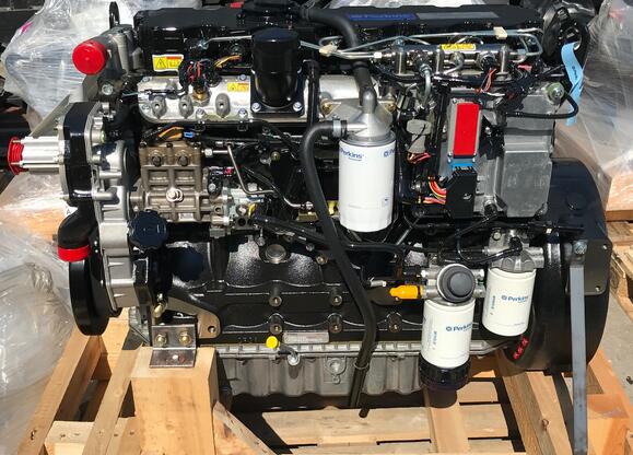
Sometime Perkins 1106D will get low power error,here is an instruction show you guide on how to solve Perkins 1106D electric power generation (EPG) low power error.
Preparations:
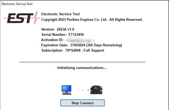
Newest Perkins EST 2023A & 2019A Full Support Free Download
Procedures:
Probable Causes
• Diagnostic codes
• ECM parameters
• Electrical connectors
• Air intake and exhaust system
• Valve lash
• Turbocharger
• Fuel supply
• Low compression (cylinder pressure)
• Individual malfunctioning cylinder
• Electronic unit injectors
Recommended Actions
NOTICE
Do not crank the engine continuously for more than 0 seconds. Allow the starting motor to cool for two inutes before cranking the engine again.
Diagnostic Codes
Check for active diagnostic codes on the electronic ervice tool. Troubleshoot any active codes before ontinuing with this procedure.
ECM Parameters
1.unsure that the fault is not a programmed arameter.
2.Use the electronic service tool to ensure that the orrect mode was selected.
3.Use the electronic service tool to verify that the orrect engine rating has been provided.
4.Use the electronic service tool to verify the aximum engine speed limit.
5.Use the electronic service tool to reset the arameters to the OEM specifications.
6.Ensure that the repairs have eliminated the poor erformance.
7.If the repairs have not eliminated the faults roceed to “Electrical Connectors”.
Electrical Connectors
1.Turn the keyswitch to the ON position.
2.Use the electronic service tool to verify that the ntake manifold pressure is 0 kPa (0 psi). Check the 5 Volt sensor supply for the intake manifold ressure. Refer to Troubleshooting, “5 Volt Sensor Supply Circuit – Test”.
3.Use the electronic service tool to verify the throttle osition status.
4.Run the engine until the speed is equal to the aximum no-load speed.
5.If the maximum no-load speed of the engine is rratic refer to Troubleshooting, “Speed Demand
Circuit (Analog) – Test” or Troubleshooting, “Speed emand Circuit (Digital) – Test”.
6.If the fault has not been eliminated, proceed to Air Intake and Exhaust System”.
Air Intake and Exhaust System
1.Check the air filter restriction indicator, if equipped.
2.Ensure that the air filter is clean and serviceable.
3.Check the air intake and the exhaust system for he following defects:
• Blockages
• Restrictions
• Damage to the air intake and exhaust lines and oses
4.Make all necessary repairs to the engine.
5.If the fault has not been eliminated, proceed to Valve Lash”.
Valve Lash
1.Check the valve lash and reset the valve lash, if ecessary. Refer to Systems Operation, Testing and Adjusting, “Engine Valve lash – Inspect and Ajust”.
2.If the repair does not eliminate the fault proceed o “Turbocharger”.
Turbocharger
Note: The turbocharger that is installed on this ngine is a nonserviceable item. If any mechanical fault exists, except for the wastegate actuator, then he turbocharger must be replaced. The wastegate ctuator can be replaced.
1.Ensure that the mounting bolts for the turbocharger re tight.
2.Check that the oil drain for the turbocharger is not locked or restricted.
3.Check that the compressor housing for the urbocharger is free of dirt and debris.
4.Check that the turbine housing for the turbocharger s free of dirt and debris.
5.Check that the turbine blades rotate freely in the urbocharger.
6.Ensure that the wastegate on the turbocharger is djusted correctly. Refer to Systems Operation,Testing and Adjusting, “Turbocharger – Inspect”.
If the wastegate actuator is faulty, replace the astegate actuator. Refer to Disassembly and
Assembly, “Turbocharger – Disassemble” and isassembly and Assembly, “Turbocharger -Asemble”.
7If necessary, replace the turbocharger. Refer o Disassembly and Assembly, “Turbocharger
– Remove” and Disassembly and Assembly,“Turbocharger – Install”.
8Check that the repairs have eliminated the faults.
9If the fault has not been eliminated, proceed to Fuel Supply”.
Fuel Supply
1.Visually check the fuel tank for fuel. The fuel auge may be faulty.
2.Ensure that the fuel supply valve (if equipped) is n the full OPEN position.
3.If the temperature is below 0 °C (32 °F), check or solidified fuel (wax).
4.Check the primary filter/water separator for water n the fuel.
5.Check for fuel supply lines that are restricted.
6.Check that the low pressure fuel lines are tight nd secured properly.
7.Check the fuel filters.
8.Check the diesel fuel for contamination. Refer to system Operation, Testing and Adjusting, “Fuel Quality – Test”.
9.Check for air in the fuel system. Refer to Systems Operation, Testing and Adjusting, “Air in Fuel -Test”.
10.Ensure that the fuel system has been primed.Refer to Systems Operation, Testing and Adjusting, “Fuel System – Prime”.
11.Check the fuel pressure. Refer to System
Leave a Reply